Field principle
This reference uses simplified educational symbols. Real component standards and regional symbol styles differ; always check the device datasheet and schematic legend before connecting anything.
On this page
Common passive and source symbols
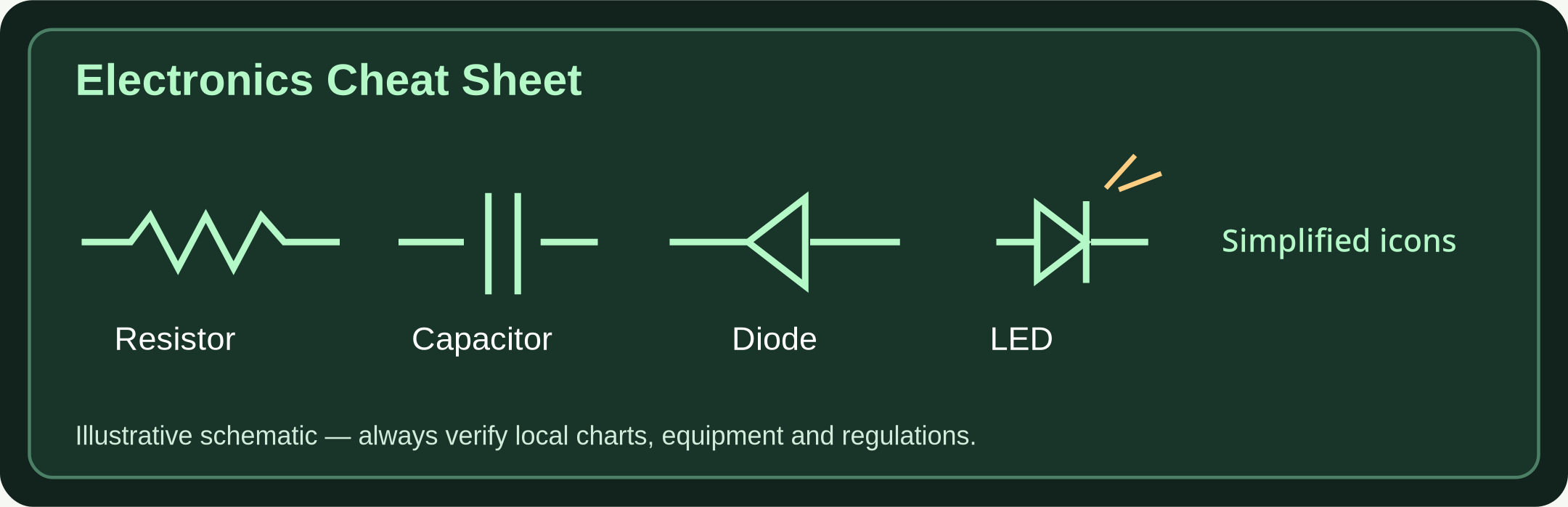
- Resistor — zigzag or rectangle: Limits current or divides voltage. Value is measured in ohms (Ω).
- Variable resistor / potentiometer: Arrow across resistor: adjustable resistance or voltage divider.
- Capacitor — two plates: Stores electric charge; polarized capacitors have polarity markings and must be oriented correctly.
- Inductor — coils: Stores energy in magnetic fields; often used in filters and tuned circuits.
- Battery — long/short parallel lines: Provides DC electrical energy; the longer line conventionally indicates positive.
- Ground / common: Electrical reference node. Signal ground does not automatically mean safe protective earth.
- Fuse: Sacrificial overcurrent protection; value and type matter.
Active components and controls
- Diode: Conducts primarily one way; line on symbol identifies cathode.
- LED: Light-emitting diode with arrows pointing outward; requires suitable current limiting.
- NPN / PNP transistors: Three terminals; emitter arrow direction distinguishes type (NPN points out, PNP points in).
- Switch, normally open: Closes a circuit when activated; momentary switch returns when released.
- Antenna / transformer / speaker: Input/output and coupling symbols vary; check the schematic key.
Reading a circuit safely
- Start at the power source: Find battery positive, return, ground symbols and expected polarity.
- Trace connections: A junction dot indicates connected wires; crossed lines without a dot often do not connect, depending on drawing convention.
- Check ratings: Match resistor wattage, LED current, capacitor voltage and supply polarity to the parts.
- Use extra-low voltage: Build learning circuits with isolated low-voltage battery sources only; never experiment on mains or rescue transmitter circuits.
Quick component checklist
| Marking | Meaning | Safe first check |
|---|---|---|
| R | Resistor | Resistance and power rating |
| C | Capacitor | Voltage rating and polarity |
| L | Inductor | Inductance and current |
| D / LED | Diode / LED | Polarity and current limit |
| Q | Transistor | Part number and pinout |
| F | Fuse | Approved type and rating |
Further reading & source material
Use these sources to validate local rules, technical standards and updates. No emergency article replaces official alerts or trained responders.